 Loading... Please wait...
Categories
Popular Brands
Our Newsletter
- Home
- Cycle Stop Valve
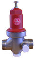
Cycle Stop Valve
Models: CSV1 CSV1A CSC1 Coupling
This is how a cycle stop valve (CSV) works: It is installed between the pump and the pressure switch/tank combination. The pressure switch and the CSV are adjusted to work with each other (sometimes only the pressure switch is adjustable). As water is used, the pressure in the well tank drops as if there was no CSV present until the pressure switch turns the pump on. As the pump pressurizes the tank to the point where the pressure is nearly adequate to turn off the well pump, the CSV regulates the flow from the pump to as little as one gallon per minute (on residential models) to as much as the pump can deliver.
If there is water being used at over gallon per minute, the pump will stay on to deliver constant pressure from the pump system to the plumbing. When the water use stops, the tank is allowed to fill to an adequate pressure to satisfy the pressure switch and turn off the well pump.
It's not magic! This is a modified pressure regulator with a bypass port. It can be used with many traditional well pumps, submersible and jet, as well as boost pumps.

Advantages to a well owner:
- Inexpensive way to accomplish constant pressure
- Relatively easy to install with basic piping skills
- Allows for use of a much smaller pressure tank than without sacrificing pump system reliability. Saves money and space
- Less wear and tear on pump system components


A bit more information from the manufacturer:
The function of a Cycle Stop Valve (CSV) is to:
(1) To provide variable flow and constant pressure control more economically than VFD systems with a high degree of reliability.
(2) To replace large pressure tanks and water towers.
(3) Provide minimum flow required to cool the pump and/or motor.
(4) Provide minimum flow to replenish the pressure tank when needed.
(5) Eliminate transient pressure waves and water hammer, stop line breaks
Selecting a Cycle Stop Valve
When selecting a Cycle Stop Valve, certain information must be known:
(1) System pressure required (2) system flow required (3) maximum output pressure of the pump
These devices are known by several names. Constant Pressure Valve (or CPV), Cycle Stop Valve (or CSV), are the names most commonly used to describe a valve that mechanically controls the output flow from a pump to match the usage. These valves have no electronics. The valve mechanically senses down stream pressure, and a pilot valve or spring mechanically controls the valves position. When pressure decreases below the set point, the valve moves toward the open position. When the pressure increases above the set point, the valve moves towards the closed position. By varying the position of the valve to maintain a constant pressure, such as 50 PSI, the output of the pump exactly matches the amount of water being used. In this way, there is no excess water produced, so large pressure tanks are no longer needed to minimize cycling.
A standard pressure switch and pressure tank is used for starting and stopping the pump. The CSV is installed before the pressure tank and switch, and is usually adjusted to the middle of the pressure switch setting. For example, a CSV set at 50 PSI is used with a 40/60 pressure switch, or a CSV set at 55 PSI is used with a 50/60 pressure switch. Small or large pressure tanks can be used with these devices, and the size of the tank determines the exact pressure settings.
When a tap is opened, the compressed air in the pressure tank, forces water from the tank to supply the usage. The pressure drops from 60 to 40 PSI as the tank is emptied. This utilizes all the water stored in the pressure tank, and keeps the pump from having to start for small, intermittent uses of water. At 40 PSI, the pressure switch starts the pump. With the CSV set at 50 PSI, the pressure quickly rises to 50 PSI. The pump will continue to run, and the pressure will remain constant, as long a small amount of water (usually 1 to 5 GPM) continues to be used. This keeps the pump from cycling on and off during long showers, small irrigation zones, and low heat pump discharge rates.
When all water outlets have been closed, the CSV also closes, and a small amount of flow (1 to 5 GPM) is bypassed from the inlet to the outlet of the CSV. This bypass rate maintains proper cooling for the pump/motor while slowly filling the remainder of the pressure tank, and the pressure switch shuts off the pump at 60 PSI. The larger the pressure tank, the less number of times the pump must start for intermittent uses of water such as ice makers, rinsing toothbrushes, or flushing a toilet. The smaller the pressure tank, or the more narrow the pressure switch differential, the more often the pump will need to start but, the sooner constant pressure is achieved.
The CSV creates a mechanical soft start and soft stop, which eliminates water hammer. An electronic soft starter can be used with a CSV, but is rarely needed as the CSV minimizes the number of on/off cycles.
When the points in the pressure switch open, no voltage is maintained on the system while the pump is off. The CSV does not use any power itself when the motor is running, or when the motor is off. The power consumption of the pump/motor naturally decreases as flow is decreased with the CSV. A CSV controlled pump uses the least amount of energy per gallon when the pump is delivering maximum flow.
The pump is sized to the maximum GPM or peak requirements of the system. When using flow less than maximum pump output, the CSV reduces the output of the pump accordingly. This keeps the pump running continuously, when flow rates required are less than maximum pump output. Very small flows or leaks, (less than 1 to 5 GPM) are fed by the pressure tank, as the pump slowly cycles on and off, depending on the size of the pressure tank, and the pressure bandwidth.
Maintaining 50 PSI constant for a shower or sprinklers, can be noticeably different than an average 50 PSI, as when a pump is cycling on and off between 40 and 60 PSI. A constant 50 PSI will deliver a consistent spray pattern for sprinklers, compared to when the pressure is continually changing between 40 and 60 PSI.
Large water systems that supply multiple houses, communities, and cities, can also use CSV controls. Varying the pump flow to match the usage eliminates the need for water towers, large hydro-pneumatic tanks, or multiple pressure tanks.
There are other manufacturers of Constant Pressure Valves or CPV’s, and they use different types of controls and bypasses, and have different pressure tank size requirements than a CSV.
While the basic principle is the same, most brands of CPV’s have external or drilled hole by-passes. These type bypasses have many disadvantages compared to the non-closing type by-pass of a Cycle Stop Valve. Small debris in the water can clog a hole at any time. Also water spewing through a small hole at 200 feet per second causes minerals to precipitate out of solution, and forms scale build up. This will clog a hole the same way holes in your showerhead clog up. Also some bacteria love areas of high velocity and will also clog small holes. Either way, what looks like barnacles on a boat hull, quickly build up and clog the small hole. This small hole is responsible for the flow needed to cool the pump and motor. When this hole clogs up, the pump is destroyed in only a few minutes.
To try and prevent the hole from clogging, a much larger hole is drilled. The size of this hole is also very important. It needs to be large enough to properly cool the pump and motor but, too large and the pump will still cycle at low flow. This means the pump can still be cycled to death and the pressure is not constant. Even a larger hole will still clog it just takes it a little longer.
The Cycle Stop Valve does not have a hole to clog. It has a non-closing seat, with two half moon notches, that come together to create a hole when the valve closes. This allows the use a very small 1 GPM bypass. When the valve opens, the two half moon notches split, and any debris, scale, or buildup breaks loose and flushes away. This prevents the valve from ever clogging, while maintaining a minimum of 1 to 5 GPM. Now the pump cannot cycle, even when flow as low as 1 GPM is being used. The pump also has the required minimum of 1 to 5 GPM to remain cool, without fear of clogging a small drilled bypass hole.
The non-closing bypass of the Cycle Stop Valve makes it the only control that reacts fast enough, to have wave canceling technology, that eliminates water hammer and line breaks.
Current Top Sellers
-
1
-
2
 Cycle Stop CSC1 Coupling$37.50
 New Products
-
$37.50
-
$261.62